Variable Frequency Drives (VFDs) have transformed industrial motor control by improving process efficiency, reducing energy consumption, and enabling precise speed regulation. From textile machinery and CNC systems to pumps, compressors, and production lines, VFDs are now a standard component of modern manufacturing facilities.
However, every VFD introduces a power quality challenge: harmonic distortion.
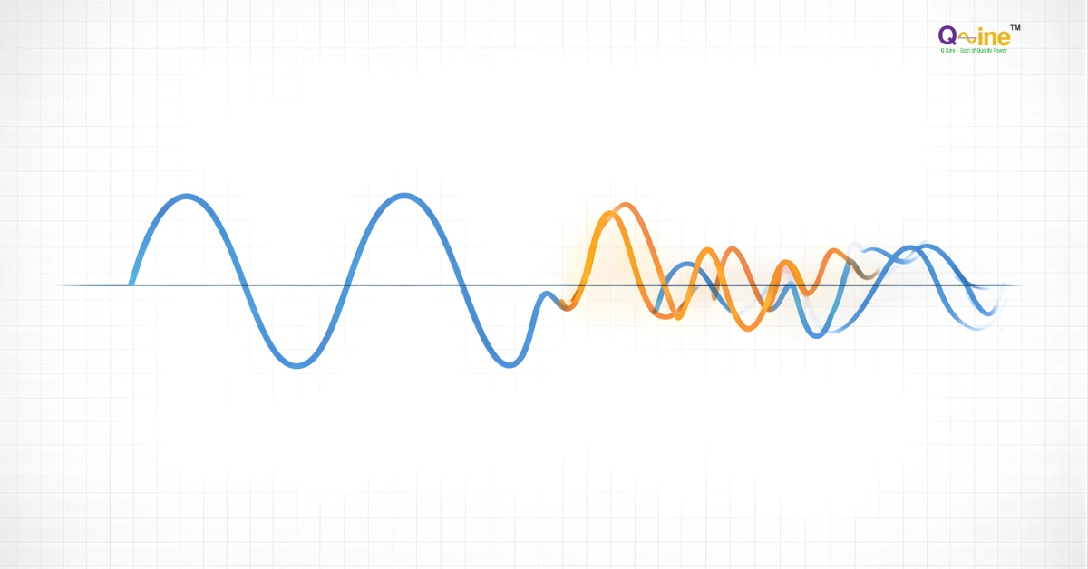
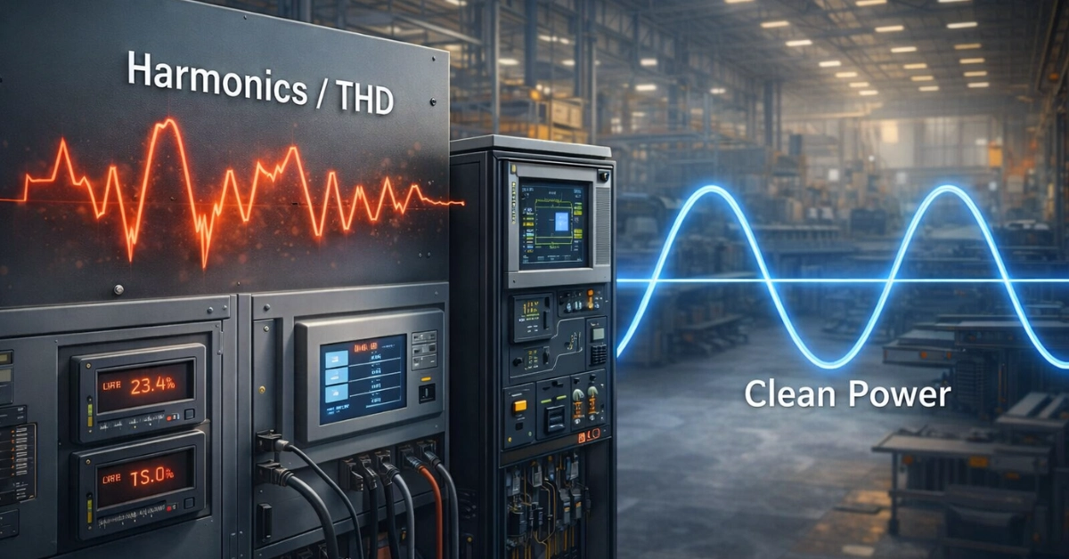
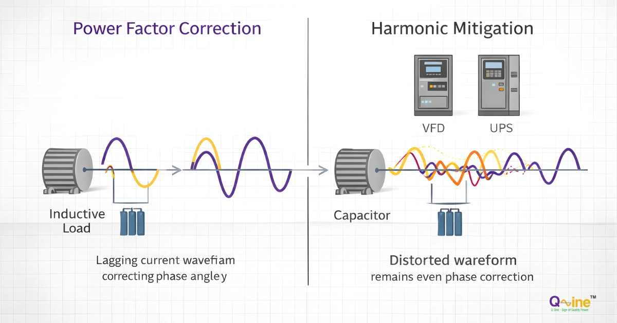
Unlike conventional linear loads, VFDs draw current in non-sinusoidal pulses because they use power electronic converters to transform fixed-frequency AC supply into variable-frequency output power. These distorted current waveforms introduce harmonic currents into the electrical system, which can affect transformers, capacitor banks, motors, protection systems, and overall plant efficiency.
For manufacturing facilities operating multiple VFDs, uncontrolled harmonic distortion can result in:
- Excessive transformer heating
- Capacitor bank failures caused by resonance
- Motor insulation and bearing stress
- Nuisance tripping of protection equipment
- Reduced electrical system capacity
- Difficulty achieving IEEE 519:2014 compliance
A properly designed harmonic mitigation strategy begins with accurate measurement. A power quality audit identifies the harmonic sources, determines compliance gaps, and helps engineers select the correct solution such as line reactors, passive filters, active harmonic filters (AHFs), or hybrid solutions.
Q Sine Energy Solutions provides power quality solutions for industrial facilities across India, including Active Harmonic Filters, Static Var Generators, APFC systems, and power quality auditing services.
Key Takeaways
- VFDs are non-linear loads that generate harmonic currents due to their rectifier-based input stage.
- Six-pulse VFDs commonly produce significant 5th, 7th, 11th, and 13th harmonic currents.
- IEEE 519:2014 defines harmonic limits at the Point of Common Coupling (PCC) based on system voltage and short-circuit ratio.
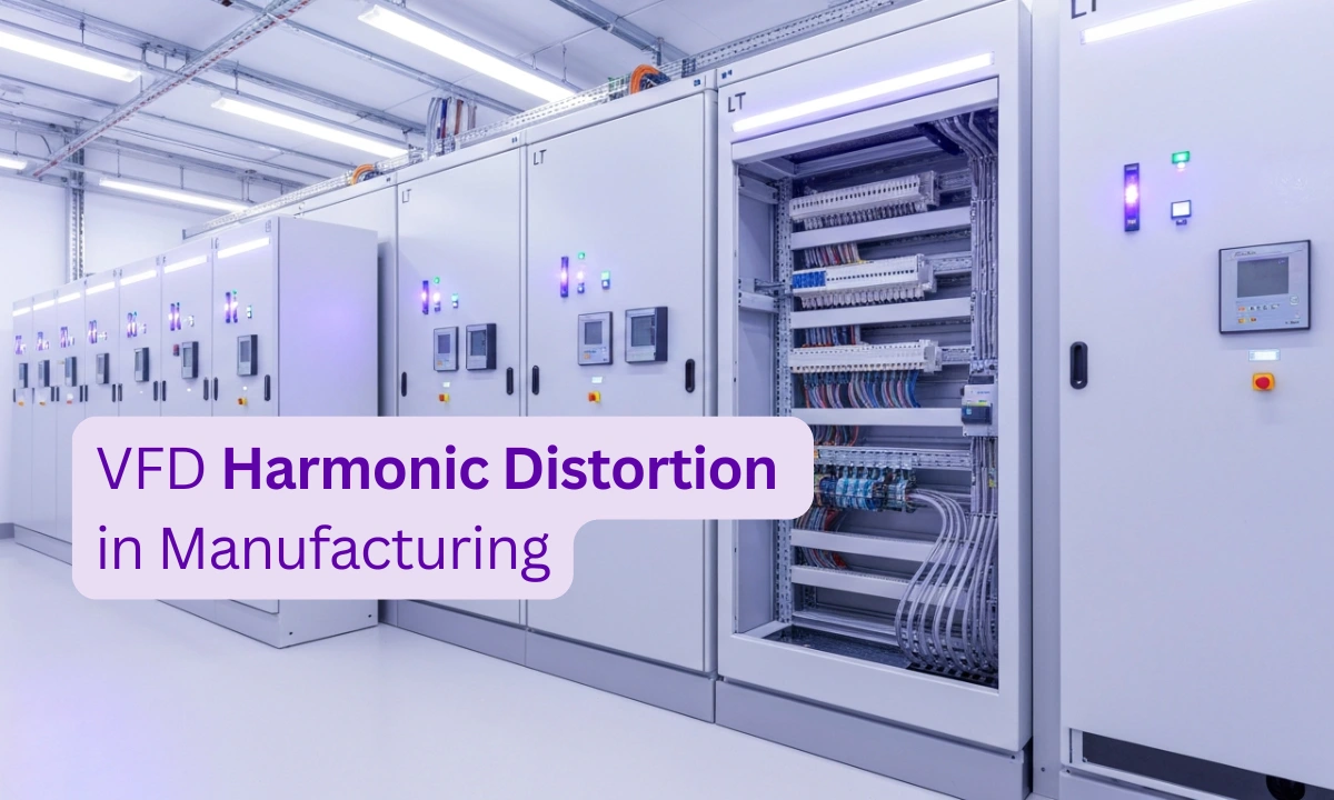
- Multiple VFDs operating together can increase harmonic distortion at the main LT panel and affect plant power quality.
- Active Harmonic Filters provide dynamic harmonic compensation for variable industrial loads.
- A power quality audit is essential before selecting harmonic mitigation equipment.
- Proper harmonic control improves equipment reliability, reduces electrical losses, and supports compliance requirements.
How Do VFDs Generate Harmonic Distortion?
A Variable Frequency Drive converts incoming AC power into DC power and then recreates a controlled AC output at the required frequency and voltage for motor operation.
The conversion process occurs in three stages:
- AC-to-DC conversion
- The input rectifier converts three-phase AC supply into DC voltage.
- Standard six-pulse rectifiers use semiconductor switches arranged in a six-pulse bridge configuration.
- DC-link energy storage
- Capacitors smooth the DC voltage and store energy.
- DC-to-AC inversion
- The inverter section uses switching devices such as IGBTs to generate variable-frequency AC output for the motor.
The input rectifier does not draw a smooth sinusoidal current. Instead, it draws short current pulses near the peaks of the supply voltage waveform. These pulses contain harmonic frequency components that flow back into the electrical network.
For a 50 Hz industrial supply, common harmonic components include:
| Harmonic Order | Frequency |
| 5th harmonic | 250 Hz |
| 7th harmonic | 350 Hz |
| 11th harmonic | 550 Hz |
| 13th harmonic | 650 Hz |
In conventional six-pulse VFDs, the 5th and 7th harmonics are typically the dominant components.
Why Multiple VFDs Increase Harmonic Problems
A single VFD may have a manageable harmonic impact depending on its size, loading, and the available short-circuit capacity of the supply system. However, industrial facilities often operate dozens or hundreds of drives simultaneously.
Examples include:
- Textile spinning and winding machines
- CNC machining centres
- Extrusion lines
- Packaging systems
- Pumps and compressors
- HVAC systems
When multiple VFDs operate from the same electrical distribution system, their harmonic currents combine at common connection points. This can increase distortion levels at the facility’s Point of Common Coupling (PCC).
The actual harmonic impact depends on several factors:
- Number and rating of VFDs
- Transformer impedance
- Utility short-circuit capacity
- Presence of line reactors or filters
- Operating load profile
- Existing capacitor banks
Therefore, harmonic levels cannot be accurately predicted only from VFD nameplate ratings. Measurement is required.
Six-Pulse vs Twelve-Pulse VFDs
Six-Pulse VFDs
The majority of industrial VFDs use six-pulse diode rectifier technology because it provides a cost-effective and reliable solution.
Typical harmonic characteristics include:
- Strong 5th and 7th harmonic currents
- Additional 11th and 13th harmonics
- Higher distortion under certain operating conditions
For many industrial installations, additional harmonic mitigation may be required to meet IEEE 519 recommendations.
Twelve-Pulse VFDs
A twelve-pulse VFD uses two six-pulse rectifiers supplied through a phase-shifting transformer. The phase displacement allows cancellation of certain harmonic components, particularly the 5th and 7th harmonics.
However, real-world performance depends on:
- Transformer phase balance
- Supply voltage quality
- Load distribution
- System impedance
Twelve-pulse systems can reduce harmonic levels significantly, but they may still require additional mitigation in installations with strict harmonic limits or large numbers of drives.
Measuring VFD Harmonic Distortion
Before selecting a harmonic filter, engineers should perform a power quality study measuring:
- Voltage THD (VTHD)
- Current THD (ITHD)
- Total Demand Distortion (TDD)
- Individual harmonic orders
- Power factor
- Load variation over time
Measurements should typically be taken at:
- Main PCC
- LT panels
- Major VFD feeders
- Large individual drive inputs
The audit data determines whether the facility requires:
- Input reactors
- Passive harmonic filters
- Active harmonic filters
- Hybrid harmonic solutions
Correct sizing based on measured harmonic current ensures effective performance and avoids unnecessary capital expenditure.
IEEE 519:2014 Requirements for VFD-Heavy Manufacturing Facilities
Understanding IEEE 519:2014 Harmonic Limits
The globally recognized reference for harmonic control in industrial power systems is IEEE 519:2014 – Recommended Practice and Requirements for Harmonic Control in Electric Power Systems.
The standard establishes harmonic limits at the Point of Common Coupling (PCC)—the point where a customer’s electrical system connects to the utility supply.
IEEE 519 considers two major parameters:
1. Voltage Harmonic Distortion (VTHD)
Voltage distortion represents the effect of harmonic currents flowing through the electrical system impedance and creating distorted supply voltage.
For systems below 69 kV, IEEE 519 generally recommends:
| Parameter | Recommended Limit |
| Individual voltage harmonic distortion | Typically ≤ 3% |
| Total Voltage Harmonic Distortion (VTHD) | ≤ 5% |
2. Current Harmonic Distortion (TDD)
Current harmonic limits are determined by the ratio between:
- ISC = Maximum short-circuit current available at the PCC
- IL = Maximum demand load current
A facility with a stronger electrical supply can generally tolerate higher current distortion than a weak electrical system.
Typical current distortion limits vary depending on the ISC/IL ratio and system voltage.
Therefore, IEEE 519 compliance cannot be confirmed only by measuring THD at individual machines. The assessment must be performed at the PCC using the correct calculation method.
How VFD Harmonic Distortion Affects Industrial Equipment
Harmonic distortion is not only a power quality measurement issue. Excessive harmonic currents create real operational problems throughout an industrial electrical system.
Transformer Heating and Reduced Capacity
Transformers are designed primarily for sinusoidal loads. Harmonic currents increase losses due to:
- Additional winding eddy current losses
- Increased stray losses
- Higher thermal stress
The severity depends on:
- Harmonic spectrum
- Transformer design
- Loading level
- Cooling conditions
Facilities with significant non-linear loads may require:
- Transformer derating studies
- K-factor evaluation
- K-rated transformers
- Harmonic filtering
K-rated transformers are specifically designed to handle increased heating effects caused by non-linear loads such as:
- VFDs
- UPS systems
- Data centre equipment
- Rectifiers
Motor Stress and VFD-Related Bearing Currents
VFDs improve motor efficiency and process control, but their high-frequency switching operation can create common-mode voltages.
These voltages may produce shaft currents that travel through motor bearings, potentially causing:
- Electrical discharge machining (EDM)
- Bearing race pitting
- Premature bearing failure
Common mitigation methods include:
- Shaft grounding rings
- Insulated motor bearings
- Proper cable grounding practices
- VFD output filters where required
Active harmonic filters primarily address current harmonics on the supply side. They should not be considered a complete solution for all VFD-related bearing current issues.
Capacitor Bank Resonance and APFC Failures
Many manufacturing facilities use Automatic Power Factor Correction (APFC) systems.
When capacitor banks are connected in systems containing VFDs, harmonic currents can interact with system impedance and create resonance conditions.
Possible consequences include:
- Excessive capacitor current
- Capacitor overheating
- Fuse operation
- APFC contactor failures
Common solutions include:
- Detuned capacitor banks
- Harmonic reactors
- Active harmonic filters
- Hybrid harmonic filter systems
A harmonic study should be performed before installing or expanding capacitor banks in VFD-heavy facilities.
Increased Electrical Losses and Power Factor Impact
Harmonic currents increase RMS current without contributing directly to useful mechanical output.
This can increase:
- Cable losses
- Transformer losses
- Generator loading
- Distribution system current
Power factor has two components:
Displacement power factor
Related to phase difference between voltage and current.
Distortion power factor
Related to waveform distortion caused by harmonics.
Modern VFDs with active front-end technology may have excellent power factor performance, while conventional diode-bridge VFDs can introduce significant distortion.
Improving harmonic distortion can therefore improve overall electrical efficiency and reduce unnecessary kVA demand.
Active Harmonic Filters vs Passive Harmonic Filters
Manufacturing plants with multiple variable-speed drives requires harmonic mitigation solutions that can handle changing operating conditions.
The two primary approaches are passive harmonic filters and active harmonic filters.
| Feature | Passive Harmonic Filter | Active Harmonic Filter |
| Operating principle | Tuned LC circuits | Power electronics-based compensation |
| Harmonic response | Fixed harmonic orders | Dynamic compensation of multiple harmonics |
| Response to load variation | Limited | Real-time adaptation |
| Resonance risk | Possible | Very low |
| Best suited for | Stable, predictable loads | Variable industrial loads |
| Expansion capability | Limited | Modular |
Why Active Harmonic Filters Are Effective for VFD Applications
Industrial plants rarely operate at a constant load.
During normal production:
- Motors start and stop
- Machine speeds change
- Production output varies
- Multiple VFDs operate at different loading levels
Because harmonic patterns change with operating conditions, fixed passive solutions may not always provide consistent performance.
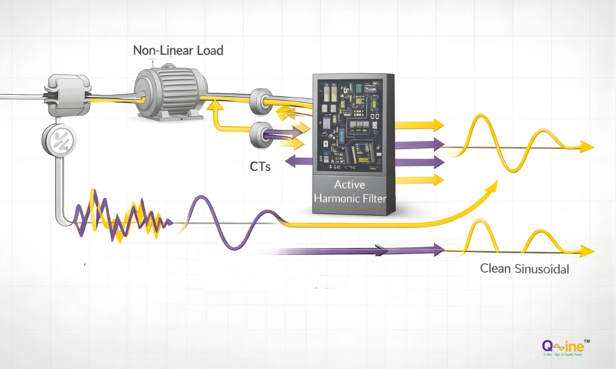
Active Harmonic Filters continuously:
- Measure load current
- Identify harmonic components
- Generate compensating currents
- Cancel unwanted harmonic currents
This makes them particularly suitable for:
- Automotive plants
- Textile industries
- Pharmaceutical manufacturing
- Metal processing
- CNC machining facilities
Steps to Achieve IEEE 519 Compliance in a VFD-Based Plant
Step 1: Perform a Power Quality Audit
The first step is measurement.
A comprehensive audit should include:
- Voltage THD
- Current THD
- Individual harmonic spectrum
- Power factor
- Load profile analysis
- PCC measurements
The audit identifies the actual harmonic sources and determines the required mitigation capacity.
Step 2: Select the Correct Mitigation Strategy
Depending on the results, solutions may include:
Line Reactors
Suitable for:
- Individual smaller VFDs
- Reducing current peaks
- Protecting drives from supply disturbances
Passive Harmonic Filters
Suitable for:
- Fixed loads
- Predictable operating conditions
Active Harmonic Filters
Suitable for:
- Multiple VFDs
- Variable production environments
- Facilities requiring dynamic compensation
Hybrid Solutions
Used where facilities require:
- Harmonic correction
- Reactive power compensation
- Existing capacitor bank integration
Step 3: Correctly Size the Harmonic Filter
AHF sizing should be based on:
- Measured harmonic current
- Required compensation level
- Future expansion plans
It should not be based only on:
- Total installed motor capacity
- Number of VFDs
- Motor horsepower ratings
Oversizing increases capital cost. Undersizing may prevent compliance.
Step 4: Verify Performance After Installation
Post-installation testing should confirm:
- Reduced harmonic levels
- Improved power factor
- Compliance status
- Equipment operating conditions
Documentation provides a baseline for future maintenance and energy management.
Conclusion
Variable Frequency Drives are essential for energy-efficient industrial operations, but their impact on electrical power quality must be managed properly.
A complete harmonic mitigation strategy combines:
- Accurate measurement
- IEEE 519-based evaluation
- Correct equipment selection
- Post-installation verification
Active Harmonic Filters provide a flexible solution for manufacturing facilities where VFD loads vary throughout production cycles.
Q Sine Energy Solutions provides power quality audits and harmonic mitigation solutions including Active Harmonic Filters, Static Var Generators, APFC systems, and industrial power quality equipment for manufacturing facilities across India.
For facilities experiencing transformer heating, capacitor failures, nuisance tripping, or power quality concerns, a detailed harmonic study is the correct starting point.
Frequently Asked Questions
What harmonic distortion does a VFD typically produce?
A standard six-pulse VFD can produce significant current distortion at its input terminals. Actual levels depend on drive design, loading, supply impedance, and whether mitigation components such as reactors or filters are installed.
In multi-drive industrial plants, cumulative harmonic distortion at distribution panels can become substantial and should be verified through measurement.
Can VFD harmonics affect electricity bills?
Yes. Harmonic currents increase RMS current and can contribute to higher apparent power demand, additional electrical losses, and reduced system efficiency.
The exact tariff impact depends on the utility regulations, billing method, and local power quality requirements. Facilities should review applicable electricity supply regulations and perform measurements before estimating savings.
Can passive filters achieve IEEE 519 compliance?
Passive filters can achieve compliance in certain applications, particularly where harmonic sources and operating conditions are stable.
However, facilities with many VFDs operating at changing loads often benefit from active harmonic filters because they provide dynamic compensation.
How is an active harmonic filter sized?
An AHF is sized according to measured harmonic current at the installation point.
The engineering process includes:
Measuring harmonic current
Identifying dominant harmonic orders
Calculating required compensation current
Considering future load expansion
What is the first step before installing a harmonic filter?
The first step is a professional power quality audit.
Without measurement data, selecting harmonic mitigation equipment becomes an estimation exercise rather than an engineering solution.
References
Continue Reading
Get free access to this article and stay updated with Q Sine's latest insights on power quality and energy solutions. No spam, ever.
You're in!
Unlocking the full article now…
Your details are safe. We never share or sell your data.