
In the rapidly evolving landscape of Indian manufacturing, where efficiency directly translates into competitive advantage, managing electrical power quality is non-negotiable. A critical metric for any industrial facility is the Power Factor (PF). A low power factor—which represents wasted energy and poor system utilization—is not just an inefficiency; it’s a financial liability, often resulting in significant penalties and higher utility charges for reactive power.
For decades, the standard solution for improving Power Factor has been the installation of Automatic Power Factor Control (APFC) panels. However, as modern industrial operations have shifted towards high-speed, dynamic machinery—think CNC machining centers, robotic welding lines, and automated press shops—the limitations of conventional APFC technology have become glaringly obvious.
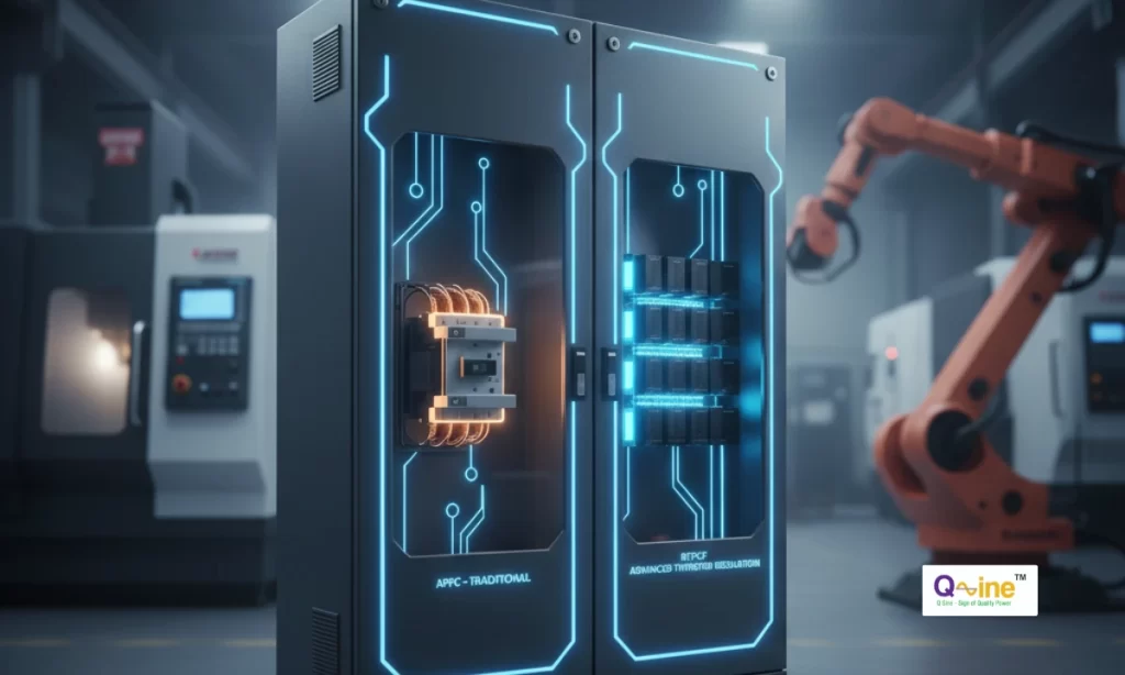
This technical comparison will highlight the key differences between traditional APFC panels and the advanced Real-Time Power Factor Correction (RTPCF) panels, demonstrating why the latter is the superior, reliable choice for today’s highly dynamic industrial environment.
To understand the fundamental concept and calculation behind Power Factor, please refer to our detailed guide on SVG Panels – Active Power Factor Correction Explained.
The Defining Challenge: Static vs. Dynamic Loads
To select the right solution, a facility must first accurately classify its electrical load profile.
1. Stable or Static Loads:
These loads consume power at a relatively constant rate with infrequent changes. Examples include continuously running motors, pumps, traditional lighting systems, and HVAC units. For these applications, the reactive power demand changes slowly and predictably.
2. Dynamic or Fluctuating Loads:
This category represents the modern industrial backbone and is the root cause of complex power quality issues. Dynamic loads involve equipment that starts, stops, or changes its power demand instantly and frequently. Common examples include:
- Welding Machines: Highly intermittent and fast-changing current draws.
- CNC Machines and Robotics: Rapid acceleration and deceleration of spindles and axes.
- Forging and Press Shops: Sudden, massive energy demands during the press cycle.
- Rolling Mills and Cranes: Continuous, fast load variations.
In facilities dominated by dynamic loads, the Power Factor can fluctuate wildly, sometimes dropping from ideal to dangerously low levels in a matter of milliseconds. This is the environment where conventional APFC systems often fail to keep up.
APFC Panel: The Limits of Conventional Switching
The Automatic Power Factor Control (APFC) panel relies on a time-tested, stage-based approach to correction.
Mechanism and Components
An APFC panel uses a microcontroller-based relay that monitors the system’s reactive power (RKVA). When the PF drops below a set threshold (e.g., 0.95), the controller signals a capacitor bank to be switched into the circuit to compensate for the reactive power.
The key limitation lies in the switching components: APFC panels traditionally use electro-mechanical contactors.
The Speed Barrier
The physical nature of a contactor—a mechanical device with moving parts—imposes a significant delay in the correction process. The time required for an APFC panel to read the reactive load, signal the controller, and physically engage the contactor can range from 3 to 60 seconds.
For a stable load, this delay is usually acceptable. However, in a dynamic environment—where the Power Factor might drop and recover dozens of times within a single minute (such as a welding operation)—a multi-second delay is fatal. By the time the APFC panel switches a capacitor bank on, the load may have already changed, leading to either:
- Under-Correction: The PF remains low, and the facility incurs penalties.
- Over-Correction: Too much capacitance is applied, causing the PF to become leading, which can also result in financial penalties and voltage rise (high voltage condition).
This slow, stage-wise switching means APFC systems struggle to maintain the desired power factor (typically near 0.99) consistently under variable load conditions.
RTPCF Panel: Instantaneous and Smart Correction
Real-Time Power Factor Correction (RTPCF) panels were developed to solve the precise challenges posed by highly fluctuating industrial loads. The “Real-Time” designation refers to the system’s ability to correct the power factor virtually instantaneously.
The Thyristor Advantage
The core technical difference is the switching mechanism. RTPCF panels utilize Thyristor Switching Modules (TSM) instead of electro-mechanical contactors. A thyristor is a solid-state electronic device with no moving parts.
This solid-state technology allows for switching speeds measured in milliseconds, not seconds. The reaction time for an RTPCF panel to switch a capacitor bank ON or OFF is often as low as 20 milliseconds (ms) and typically within the range of 40 to 60 ms. This speed is literally faster than the blink of an eye (which is around 100-400 ms), enabling the system to compensate for power fluctuations as they happen.
Transient-Free Switching
Speed is not the only benefit. A critical advantage of thyristor switching is its “zero-crossing” capability. The thyristors are precisely controlled to connect and disconnect the capacitor banks to the network at the exact moment the voltage or current crosses zero.
This smooth, transient-free switching completely avoids the common problems associated with mechanical contactors, such as:
- Arcing and Contact Bounce: Which degrades the contactor and the capacitor bank over time.
- Switching Spikes: Which can cause severe waveform distortions and transient over voltages, potentially damaging sensitive electronic equipment like PLCs and CNC controls.
By connecting and disconnecting capacitors at zero crossing, the RTPCF system protects the capacitors, the switching elements, and the entire electrical network.
A Technical Side-by-Side Comparison
The choice between APFC and RTPCF hinges entirely on the nature of your plant’s operation and your priority for reliability.
| Feature | Conventional APFC Panel | Real-Time RTPCF Panel |
| Switching Mechanism | Electro-mechanical Contactors | Solid-state Thyristor Switching Modules (TSM) |
| Response Speed | Slow (3 to 60 seconds) | Instantaneous (Less than 20 ms, often 40-60 ms) |
| Ideal Application | Stable, slow-changing loads (Pumps, continuous running motors) | Highly dynamic loads (Welding, CNC, Forging, Steel Mills) |
| Switching Transients | High risk of transients, spikes, and voltage flickering | Transient-free (Switches at zero crossing) |
| Accuracy of PF | Inaccurate for dynamic loads, high risk of penalty | Highly Accurate, consistently maintains PF close to unity (e.g., 0.995) |
| Maintenance | High (Requires regular inspection and replacement of contactors) | Low to Virtually Maintenance-Free (No moving parts) 3 |
| Equipment Protection | Lower (Risk of waveform distortion) | Higher (Reduces voltage flickering, protects sensitive electronics) |
Conclusion: Securing Your Investment and Efficiency
For a facility running purely stable loads with minimal variation, a well-designed APFC panel can still be a cost-effective solution. However, this scenario is becoming increasingly rare in modern Indian industry.
For any business dealing with frequent starts/stops, rapid load cycling, or sophisticated electronic controls, the choice is clear: RTPCF is not just an upgrade; it is a necessity.
The ability of the RTPCF panel to deliver immediate, precise, and transient-free reactive power compensation ensures that the Power Factor remains at its optimal level (often close to 0.99). This guarantees that you avoid costly penalties, maximize the capacity of your existing transformers and switchgear, and significantly increase the lifespan of your critical electrical equipment.
Furthermore, in environments where harmonics are also a concern (often the case with VFDs and other non-linear loads), RTPCF panels can be seamlessly integrated with Detuned Harmonic Filters or Active Harmonic Filters (AHF) to provide a total, clean power solution.
While the initial investment in an RTPCF system may be slightly higher than a basic APFC panel, the superior reliability, near-zero maintenance, and guaranteed penalty avoidance often translate into a faster and more compelling Return on Investment (ROI) for dynamic operations.
Learn how to manage the challenge of non-linear loads in conjunction with Power Factor Correction by reading our guide on Understanding Active Harmonic Filters.
Stop letting inefficient power management erode your profits. Contact the clean power specialists at Q Sine today to assess your load profile and design a tailored RTPCF solution that delivers real-time efficiency and guaranteed savings for your business.