You’ve installed new Variable Frequency Drives (VFDs) to improve efficiency, but suddenly your motors are overheating or breakers are tripping.
You are likely dealing with harmonics in electrical systems, a common power quality issue that appears after installing modern electronic loads like VFDs and UPS systems.
If you’re asking what is harmonics in electrical systems, the answer lies in how modern power electronics distort current and voltage waveforms.
In the world of industrial power quality, harmonics are the invisible “ghosts” in the machine. They are the primary cause of “dirty power,” leading to equipment failure and energy waste.
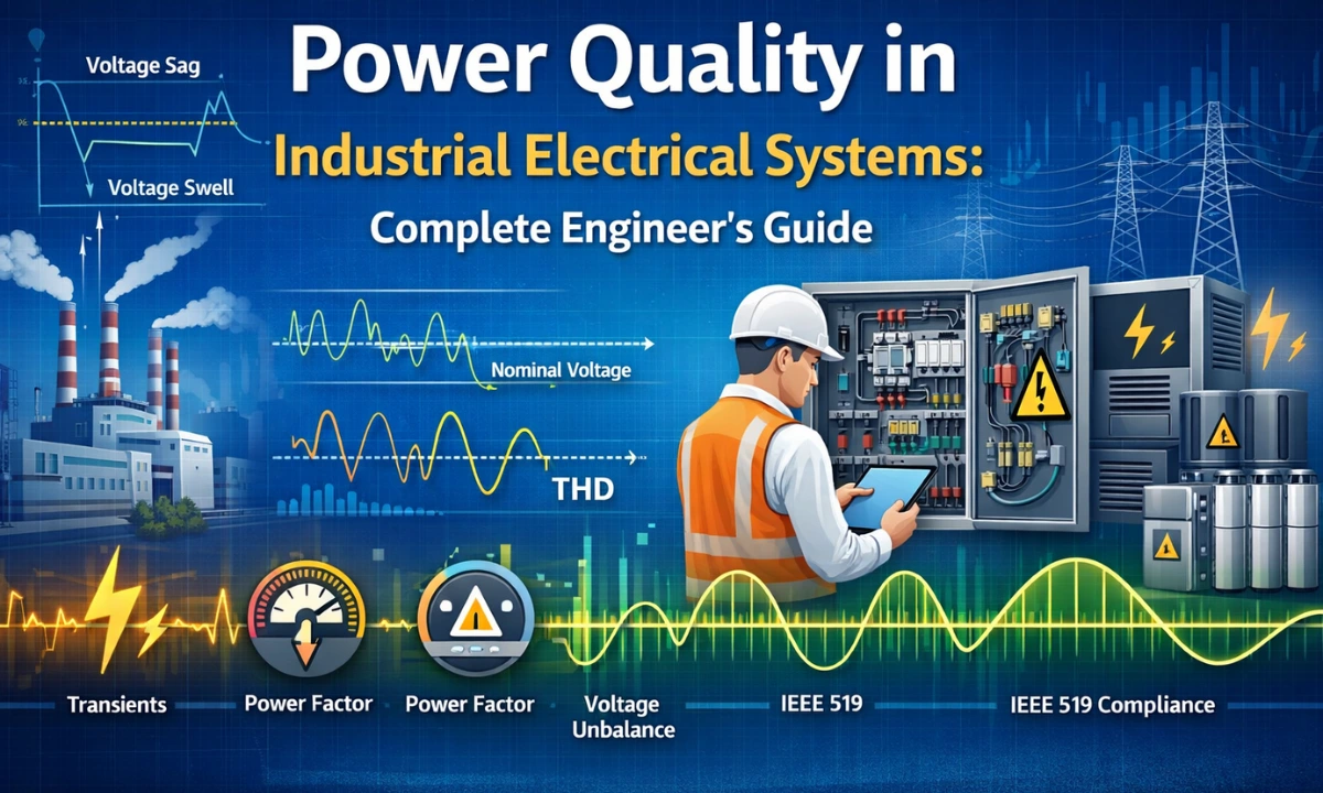
This article covers the technical definitions and physics. For a complete management strategy, read our Ultimate Guide to Harmonics in Industrial Power Systems
What are Harmonics in Electrical Systems?
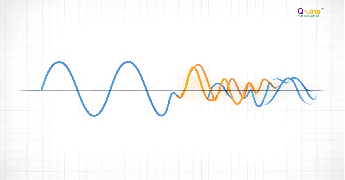
Harmonics in electrical systems are unwanted voltage or current components that occur at integer multiples of the fundamental frequency.
In practical terms, harmonics in electrical systems describe how non-linear loads distort voltage and current waveforms, leading to overheating, losses, and equipment malfunction.
When engineers ask what is harmonics in electrical, they are referring to waveform distortion caused by non-linear electrical loads such as VFDs, UPS systems, and rectifiers.
In simple terms, when engineers ask what is harmonics in electrical, they are referring to unwanted frequency components that distort the ideal sine wave of an AC power system.
The “Road” Analogy
To visualize this, think of your electrical system as a smooth, paved highway designed for cars traveling at a steady speed (the Fundamental Frequency).
Harmonics are like heavy trucks driving on that same highway, but they are bouncing and creating potholes.
- The 3rd Harmonic is a truck bouncing 3 times faster.
- The 5th Harmonic is bouncing 5 times faster.
These “bouncing trucks” damage the road surface (the wires/grid) and make the ride dangerous for regular cars (your sensitive equipment).
Fundamental Frequency vs. Harmonic Frequency

To understand harmonics, you must first understand the baseline.
The fundamental frequency is the base frequency of an AC power system (50 Hz in India and Europe, 60 Hz in the US) on which all harmonic frequencies are mathematically derived.
Harmonics are mathematically related to this base frequency. They are calculated using the formula:
$$f_{harmonic} = n \times f_{fundamental}$$
(Where ‘n’ is the integer order of the harmonic).
A clear understanding of the fundamental frequency is essential when studying harmonics in electrical systems, since every harmonic frequency is an integer multiple of this base value.
In India, most industrial facilities are connected at HT or EHT levels where harmonic compliance is closely monitored.
Common Harmonic Orders in 50 Hz Systems
| Harmonic Order | Frequency Calculation | Resulting Frequency | Common Sources |
| Fundamental | 1 X 50 Hz | 50 Hz | Grid Supply |
| 3rd Order | 3 X 50 Hz | 150 Hz | 1-Phase Loads (PCs, LED Lights) |
| 5th Order | 5 X 50 Hz | 250 Hz | 3-Phase VFDs, UPS (6-Pulse) |
| 7th Order | 7 X 50 Hz | 350 Hz | 3-Phase VFDs, UPS (6-Pulse) |
The 5th and 7th harmonics are the most common troublemakers in industrial environments because they are typically generated by standard 6-pulse drives.
The Source: Linear vs. Non-Linear Loads
Why do we have harmonics now, when we didn’t 30 years ago? The answer lies in the type of electrical loads we use.
1. Linear Loads (The Old Way)
- Examples: Incandescent light bulbs, standard heaters, and simple induction motors.
- Behavior: The current they draw follows the voltage waveform smoothly. If the voltage is a sine wave, the current is a sine wave. No harmonics are generated.
2. Non-Linear Loads (The Modern Way)
- Examples: VFDs, LED drivers, Computers, UPS systems, Battery Chargers.
- Behavior: These devices do not draw current continuously. Instead, they “sip” power in abrupt pulses. These rapid on-off pulses distort the waveform, creating harmonic currents.
Learn More: See exactly how VFDs create these pulses in our Causes of Industrial Harmonics section.
Understanding Total Harmonic Distortion (THD)

Engineers need a single number to tell them how “bad” the power quality is. That number is Total Harmonic Distortion (THD).
In real-world installations, high THD values are a direct indicator of severe harmonics in electrical systems, especially in facilities dominated by power electronic
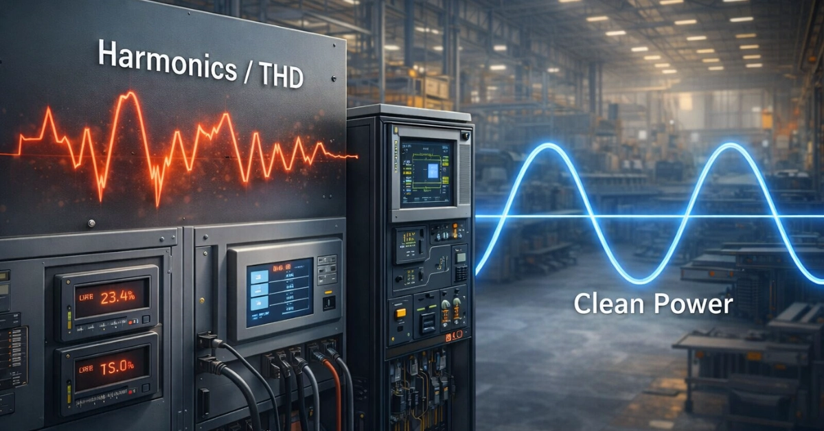
THD is a percentage that compares the “noise” (harmonics) to the “signal” (fundamental frequency).
- 0% THD: A perfect, pure sine wave.
- High THD: A jagged, distorted wave.
THD-v vs. THD-i: What’s the Difference?
- Current THD (THD-i): This measures the distortion injected by your equipment (the source).
- Voltage THD (THD-v): This measures the resulting distortion on the grid (the consequence).
According to IEEE 519 standards, a Voltage THD (THD-v) of under 5% is generally considered acceptable. If your THD-v exceeds 8%, you are at high risk of equipment failure and voiding manufacturer warranties.
In THD in power electronics, Total Harmonic Distortion quantifies how much harmonic current or voltage is present relative to the fundamental component.
THD = √(I₂² + I₃² + I₄² + …) / I₁ × 100%
Why Should You Care? (Brief Effects)
Harmonics are not just “theoretical” noise. They cause real, physical damage to your facility.
- Skin Effect: High-frequency harmonic currents travel on the outer surface of cables, effectively reducing the wire’s capacity and causing overheating.
- Transformer Failure: Harmonics generate excessive heat in transformer windings (Eddy Current Losses), leading to failure even at 50% load.
- Power Factor Penalties: Harmonics can confuse utility meters and lower your True Power Factor, which directly increases the kVAh billing value.
- Warning: Thinking of using standard capacitors to fix this? Don’t. Capacitors can amplify harmonics through resonance. Read our comparison Power Factor Correction vs. Harmonic Mitigation
How Do We Fix It?
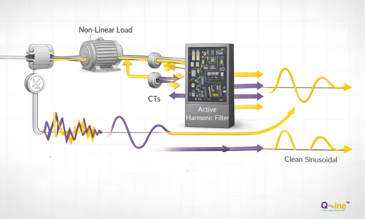
You can’t fix what you can’t measure. The first step is always identifying which harmonic orders (5th, 7th, 11th, etc.) are present in your system.
Once identified, the industry standard for modern, dynamic plants is the Active Harmonic Filter (AHF). Unlike older passive filters that are “tuned” to one frequency, an AHF actively injects canceling current to eliminate ALL harmonic orders simultaneously.
See the Solution: Discover how Active Harmonic Filter Panels eliminate distortion instantly.
Conclusion
Harmonics in electrical systems are simple physics, multiples of the fundamental frequency; but they have expensive consequences. If your Fundamental Frequency is the clean stream, harmonics are the pollution clogging the flow.
High THD is invisible to the naked eye but obvious to a Power Quality Analyzer.
Don’t wait for a failure.
At Q Sine, our engineering team specializes in diagnosing and curing “polluted power.”
Book a Power Quality Audit to measure your THD levels today.
Frequently Asked Questions
What is the definition of harmonics in electrical systems?
Harmonics are voltage or current frequencies that are integer multiples of the fundamental system frequency (e.g., 150Hz in a 50Hz system). They are generated by non-linear loads like VFDs and cause power quality issues.
What is the formula for fundamental frequency?
The fundamental frequency is the lowest frequency of a periodic waveform. In electrical power systems, this is fixed at 50 Hz (India/Europe) or 60 Hz (USA). All harmonic frequencies are calculated as $$f_{harmonic} = n \times f_{fundamental}$$
What is a safe level of THD?
Generally, Voltage THD (THD-v) should be kept below 5% at the point of common coupling, according to IEEE 519 standards. Current THD limits vary based on load size but should typically be monitored if they exceed 8-10%.
Continue Reading
Get free access to this article and stay updated with Q Sine's latest insights on power quality and energy solutions. No spam, ever.
You're in!
Unlocking the full article now…
Your details are safe. We never share or sell your data.